



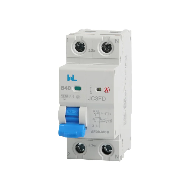





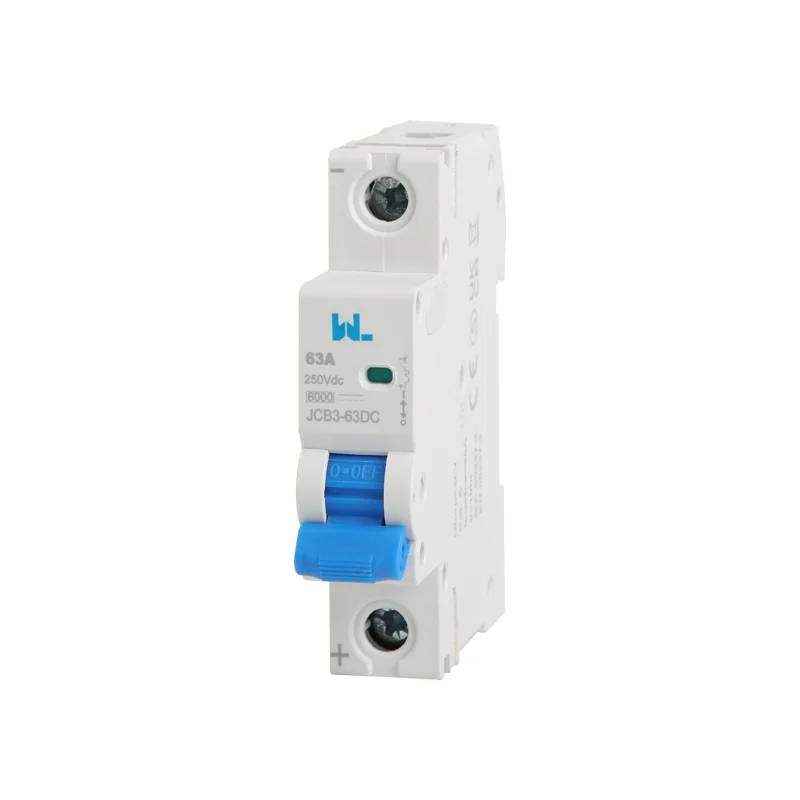
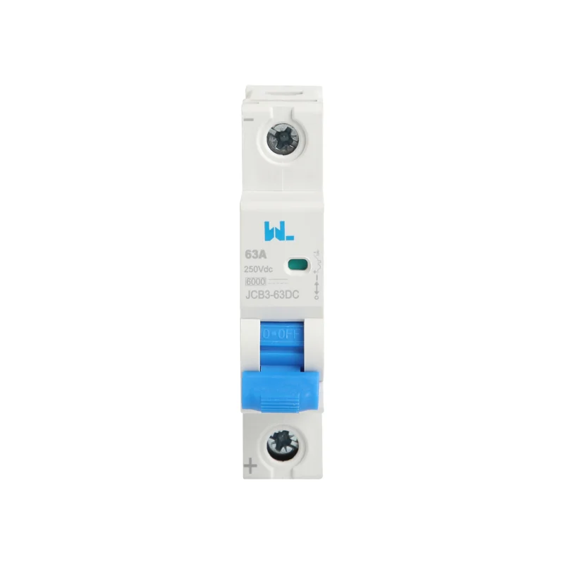
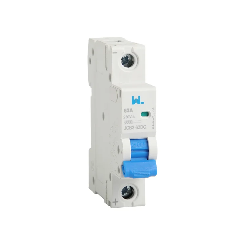
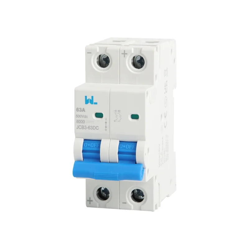
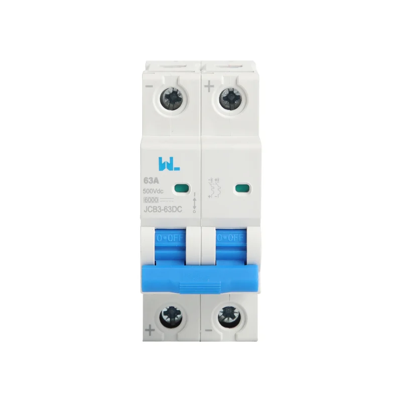
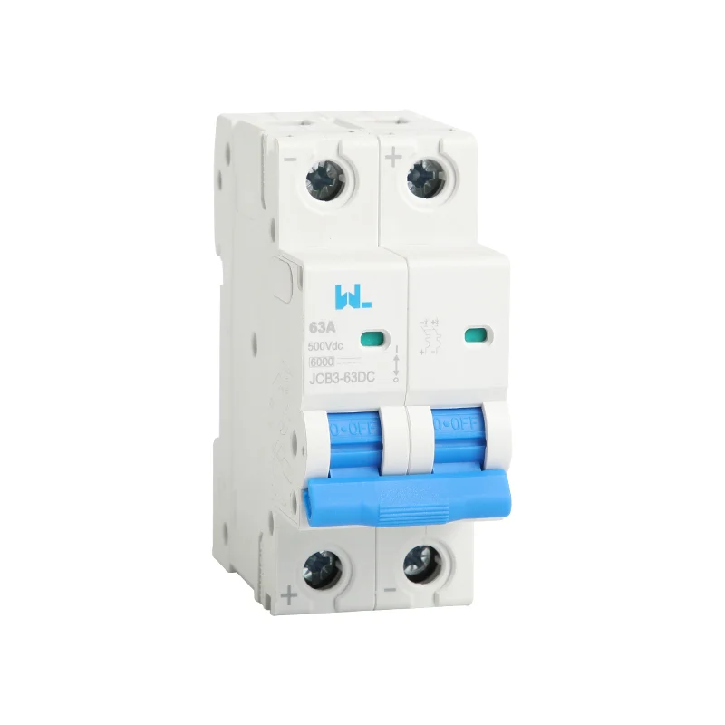
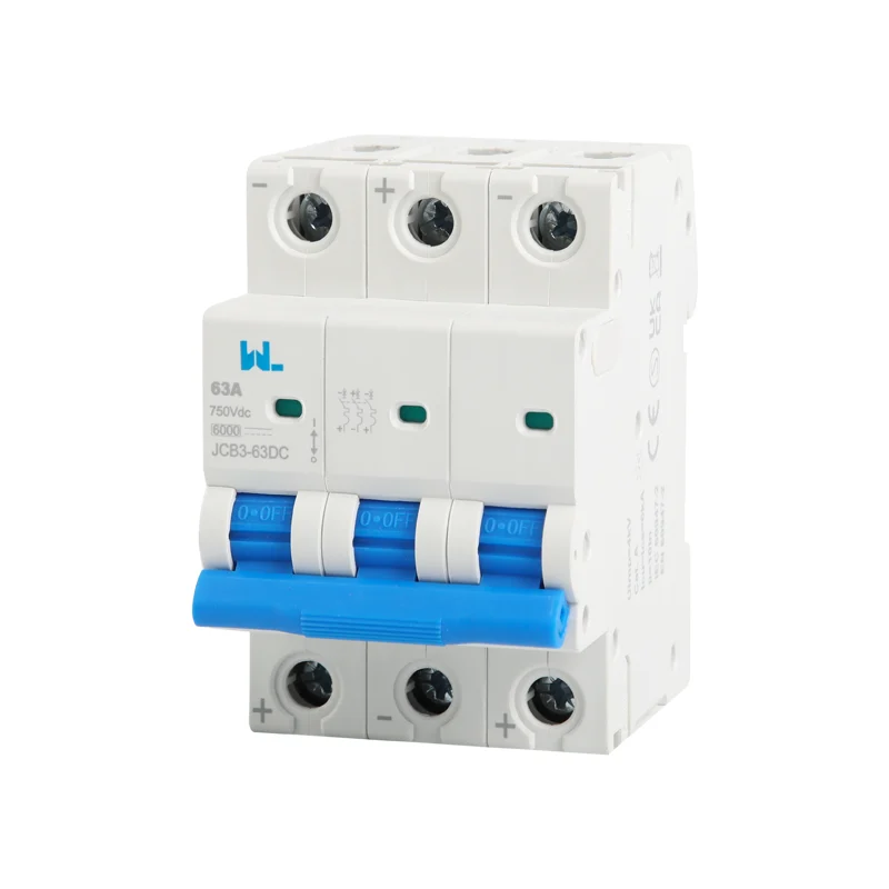
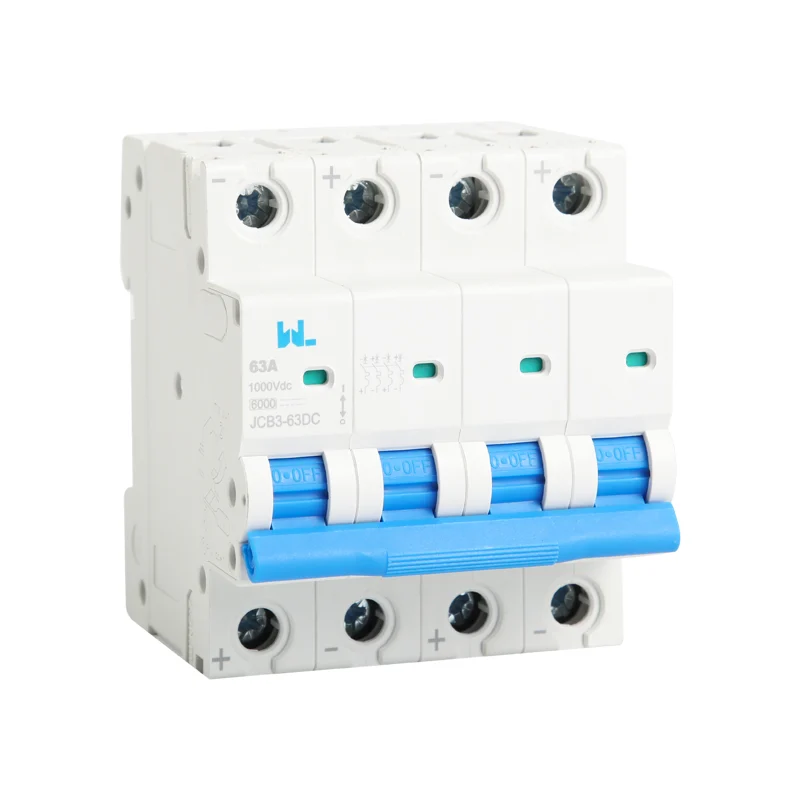
JCB3-63DC DC miniature circuit breaker
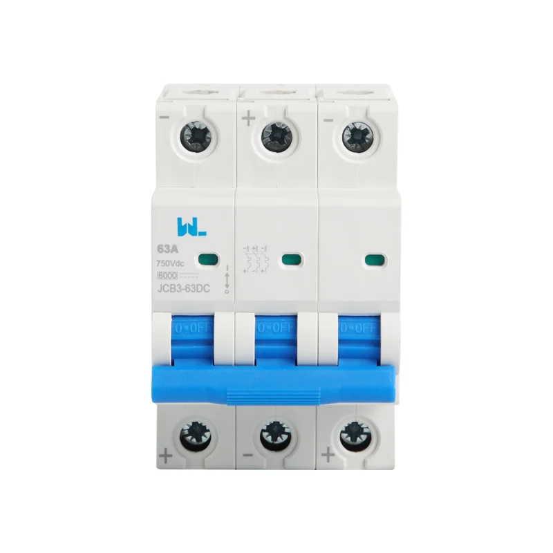
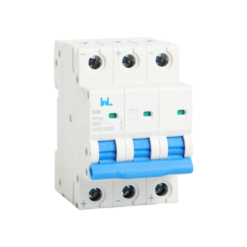
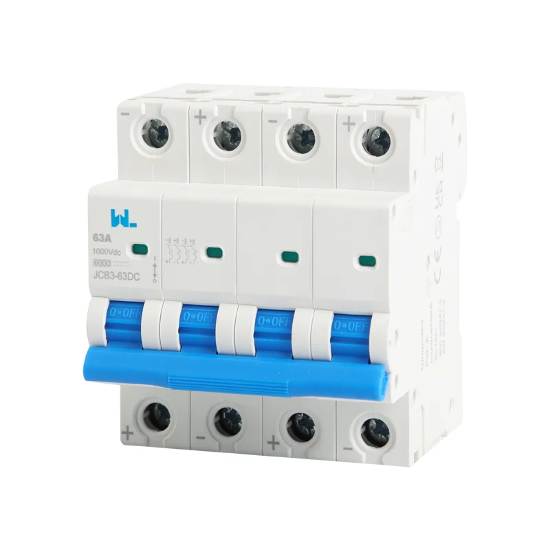
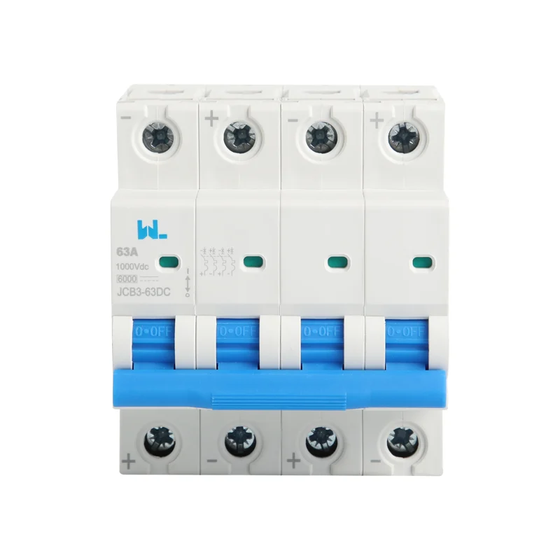
The JCB3-63DC protects communication, photovoltaic and energy-storage DC circuits against overloads and short circuits. Its table lists currents from 6 A to 63 A, B and C trip curves, and 1P through 4P versions. Check polarity and the wiring diagram for the version being supplied.
- DC overload and short-circuit protection
- 6kA listed breaking capacity
- Listed current range: 6–63A
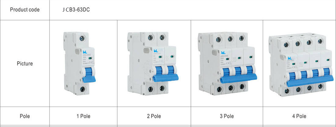
- 1P, 2P, 3P and 4P configurations
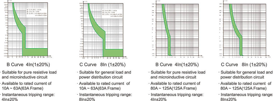
- B and C trip curves
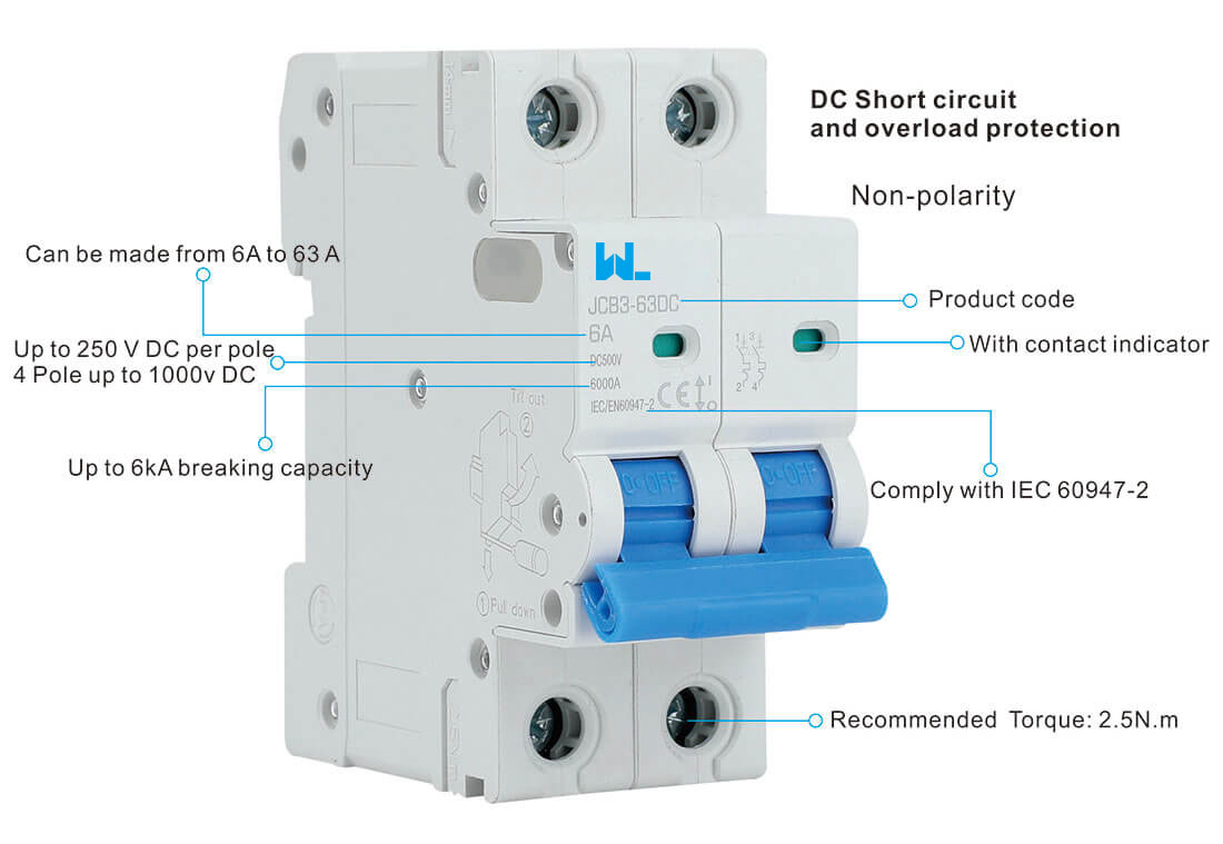
- Contact indicator: green = OFF, red = ON
- 35mm DIN-rail mounting
- For solar PV and energy-storage circuits
PRODUCT OVERVIEW
JCB3-63DC Circuit Breaker for PV and Communication Systems
The JCB3-63DC uses a thermal release for overloads and an electromagnetic release for short circuits. It is used in communication, photovoltaic and energy-storage DC circuits. The contact indicator provides a visible reference for the device state.
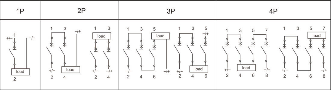
The breaker mounts on a DIN rail. Before connecting it, check the terminal markings and the wiring diagram for the supplied version. Published polarity descriptions differ, so current direction must be confirmed for the actual device.
JCB3-63DC Arc Control, Locking and Terminal Separation
- Thermal and magnetic protection
- The thermal release responds to sustained overloads, while the electromagnetic release responds to short circuits. The supplier also describes an arc-extinguishing system and flash barriers for interrupting the DC current.
- OFF-position locking and indication
- The catalogue describes a padlocking device for holding the breaker OFF during inverter maintenance. The contact indicator shows green for OFF and red for ON. Use the required isolation procedure as well as the mechanical lock.
- Inter-pole barriers and busbars
- Three inter-pole barriers are described for separating adjacent connectors. Pin-type and fork-type busbar connections are listed. Match the busbar and barrier arrangement to the supplied breaker and leave the required terminal clearances.
- Current limiting and current direction
- The supplier lists current limiting class 3 and describes non-polarity and bidirectional protection. Confirm current direction from the supplied device markings and wiring instructions. For coordination with a backup fuse, use data for the specific fuse–breaker combination.
TECHNICAL DATA
JCB3-63DC DC Miniature Circuit Breaker Specifications
The table lists current, pole and DC voltage options. Keep the voltage rating and pole-wiring requirements together when selecting a version; ask W9 Group to resolve any conflicting product information before ordering.
| Product code | JCB3-63DC | |||
| Pole | 1 Pole | 2 Pole | 3 Pole | 4 Pole |
| Standard | IEC/ EN 60947- 2 | |||
|
Electrical features |
Rated current In (A) | 6 , 10, 16, 20 , 25 , 32, 40, 50 , 63 | ||
| Rated voltage Ue(V) | 1P:DC250V, 2P:DC500V, 3P:DC 750V, 4P:DC1000V | |||
| Insulation voltage Ui (V) | 1000V | |||
| Rated impulse withstand voltage Uimp (V) | 4000V | |||
| Rated breaking capacity | 6 kA | |||
| Rated impulse withstand voltage( 1 . 2/ 50) Uimp (V) | 4000 | |||
| Pollution degree | 2 | |||
| Thermo- magnetic release characteristic | B Curve , C Curve | |||
|
Mechanicalfeatures |
Electrical life | ≥1500 | ||
| Mechanical life | ≥20000 | |||
| Contact position indicator | Yes | |||
| Protection degree | IP 20 | |||
| Reference temperature for setting of thermal element(℃) | 30 | |||
| Ambient temperature (with daily average ≤35℃) | – 5…+40 ℃ | |||
| Storage temperation (℃) | -25 . . . + 70 ℃ | |||
|
Installation |
Terminal connection type | Cable/ U-type busbar/ Pin-type busbar | ||
| Terminal size top/ bottom for cable | 25mm2 / 18-4 AWG | |||
| Terminal size top/ bottom for busbar | 10mm2 / 18- 8 AWG | |||
| Tightening torque | 2. 5 N*m / 22 In-Ibs. | |||
| Mounting | On DIN rail EN 60715 ( 35mm) | |||
|
Combination with accessories |
Auxiliary contact | Yes | ||
| Shunt release | Yes | |||
| Under voltage release | Yes | |||
| Alarm contact | Yes | |||
PRODUCT DETAILS
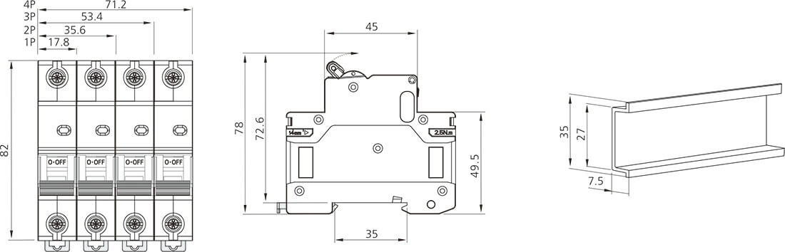
JCB3-63DC Product Illustrations and Technical Drawings
Original illustrations from the supplier’s product page, including the labels and figures printed on each image. Open an image to read the details at full size.
Product features
Pole configurations
Tripping characteristic curves
Dimensions and DIN-rail profile
Wiring diagram
SELECTION GUIDE
How to Choose a JCB3-63DC DC Circuit Breaker
Work through these four checks before ordering. They cover the circuit rating, protection requirements and installation fit.
JCB3-63DC Applications in Solar and Energy Storage
The supplier places this breaker in solar PV and energy-storage circuits, particularly between batteries and hybrid inverters. Consider both normal power flow and possible reverse fault current when reviewing the circuit arrangement.
Choose the current and B or C curve
Use the listed current options to select a rating for the load and cable. Compare the B or C trip curve with the load starting current and other protective devices.
Match DC voltage to pole wiring
Choose the pole arrangement for the system voltage. Ask for the required series connection and earthing diagram rather than assuming how the poles should be connected.
Check polarity before connection
Published information gives different polarity descriptions. Ask for the terminal markings and permitted current direction for the version being supplied.
Check the DC rating and accessories
Give the available short-circuit current and any required auxiliary functions. Ask for the relevant DC test conditions and the compatible accessory codes.
Plan the Complete PV and Battery Protection Scheme
The supplier’s application notes discuss an AC-side residual-current device and DC-side insulation monitoring or earth-fault protection, as required by the system design. These perform different jobs from the breaker’s overload and short-circuit functions.
Do not rely on the breaker alone to cover every double-fault condition. Investigate and clear a detected fault before returning the circuit to service. Read the pole connections, earthing arrangement and current direction together when selecting the protection scheme.
ABOUT W9 GROUP
Buying JCB3-63DC Circuit Breakers from W9 Group
Zhejiang W9 Group Technology Co., Ltd. supplies low-voltage electrical products. Contact W9 Group about JCB3-63DC specifications, installation documents or branding requirements for your order.

RELATED RESOURCES
JCB3-63DC Datasheets and Technical Support
Need a JCB3-63DC datasheet, wiring diagram or trip curve? Contact technical support with the current rating and pole configuration you need. You can also browse the product range and the W9 Group download centre below.
RELATED PRODUCTView the JCB1-125DC product pageReview this model separately to compare its ratings and connection requirements.
DOCUMENTSVisit the download centreBrowse available documents. If the JCB3-63DC file is missing, contact technical support.
BUYER FAQ
JCB3-63DC DC Circuit Breaker FAQs
Answers to common questions about ratings, wiring, installation and ordering.
Which current ratings are listed?
The electrical table lists 6, 10, 16, 20, 25, 32, 40, 50 and 63 A. Other descriptions mention lower ratings; ask W9 Group to confirm availability before ordering one.
Does every pole version have the same DC voltage rating?
No. The table gives different voltages for different pole arrangements. Use the voltage and connection diagram for the version you select.
Is the JCB3-63DC polarity sensitive?
Published descriptions conflict on this point. Ask W9 Group to confirm the terminal polarity and permitted current direction for the supplied device before installation.
Is the listed 6 kA capacity suitable for my circuit?
Check the DC voltage, pole wiring and test conditions associated with the 6 kA rating. The breaker must be suitable for the short-circuit current available at your installation.
Does it also provide residual-current or insulation monitoring?
Those functions are not included in the stated overload and short-circuit protection. Follow the system design for any additional monitoring or protection devices.
Which standards and accessories apply?
Published standard references differ. Ask for the test documents for the exact model and the product codes for any required auxiliary contact, alarm or release.
What should I send for a JCB3-63DC quotation?
Send W9 Group your required DC voltage, rated current, pole configuration and trip curve, quantity and destination country. Include any wiring, accessory or documentation requirements. Ask for price and delivery time for the proposed version.
PRODUCT ENQUIRY
Get a Quote for JCB3-63DC DC Circuit Breakers
Send W9 Group your required DC voltage, rated current, pole configuration and trip curve, quantity and destination country.
Include any wiring, accessory or documentation requirements. Ask for price and delivery time for the proposed version.